
Instruction Sheets for Part Number AOM-06AT
Technical Articles for Part Number AOM-06AT
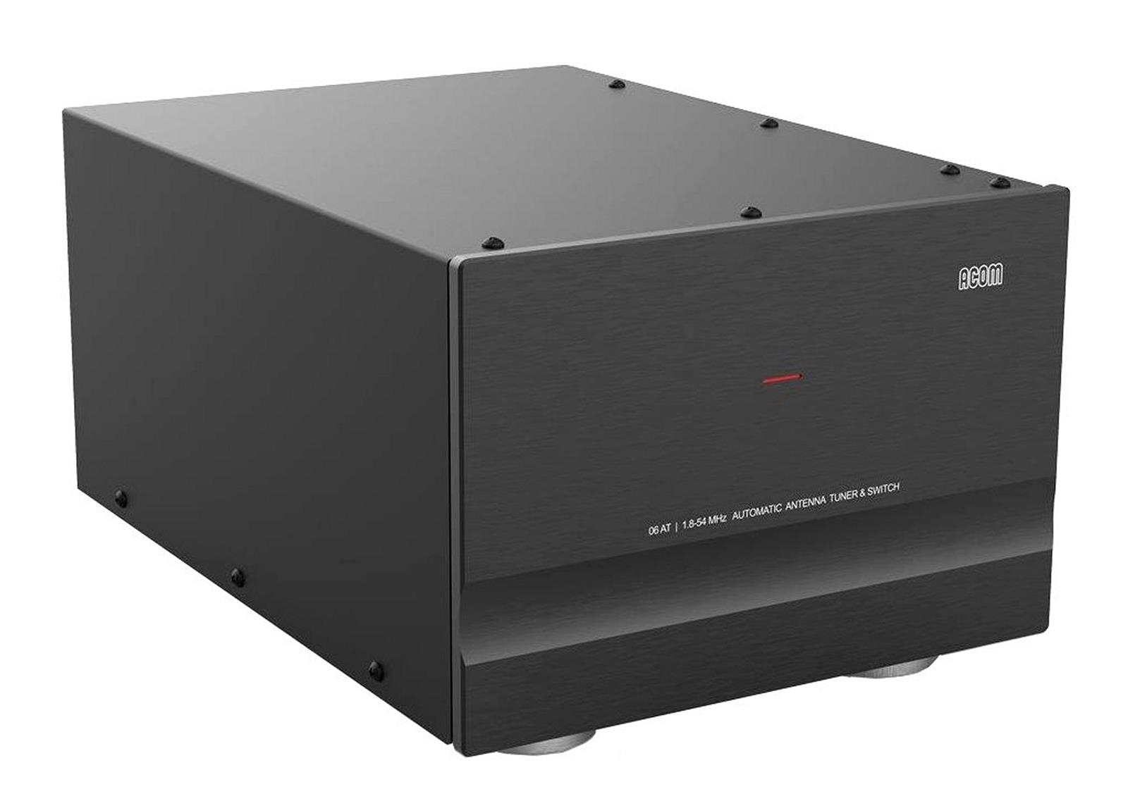
ACOM 06AT Automatic Antenna Tuners
Antenna Tuner, Automatic, 1,500W PEP, 1.8-54 MHz, Works with ACOM Solid State Amplifiers, 4 SO-239 Outputs, Power and Control by Amp, Each
See More Specifications
Estimated Ship Date from Ohio: Today Would you rather pick it up?
Consider an Open Box Item Get instant savings on this product!

Overview
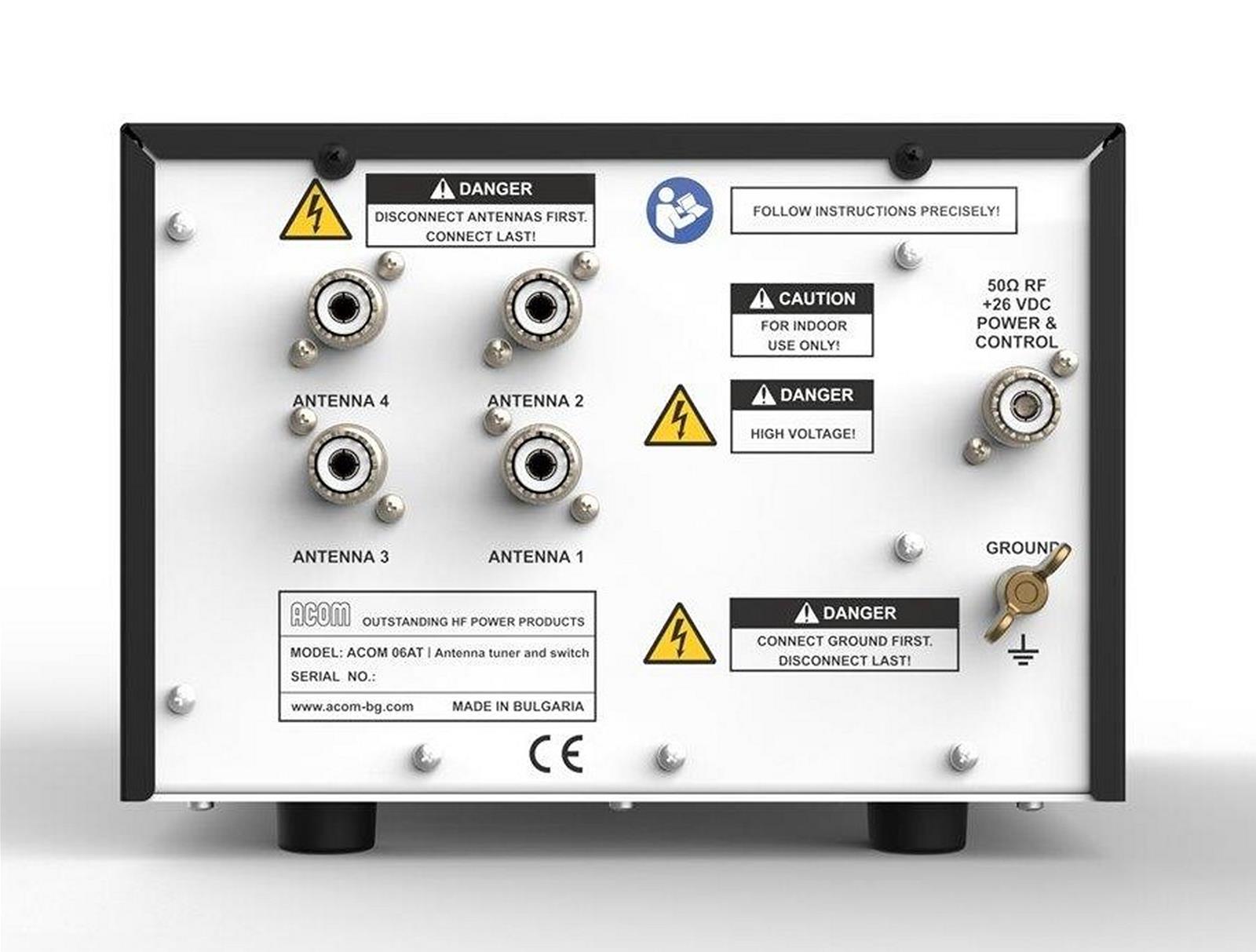
This tuner will automatically select one of the four available antenna outputs (as assigned by the operator) and matches the impedance of the chosen antenna output by transforming it to 50 Ohms with SWR below 1.5 at the tuner input (typically below 1.3), providing an optimum load impedance for the amplifier.
Automatic Antenna Matching provides automatic or manual antenna switching along with automatic antenna impedance matching to the ACOM solid state amplifiers, controlled entirely from the amplifier's front panel and the transceiver frequency, via CAT, COM or CI-V interface cable (not supplied).
With its selectable frequency segments, the operator can select between four typical antenna profiles according to the bandwidth of the connected antenna: Narrow, Normal - Regular, Broadband – Wide and Fixed frequency can be used so the operator can adapt the frequency segment width to the specific antennas bandwidth. BYPASS mode is also available.
The ACOM 06AT operates in two tuning modes: Full tuning mode, a basic matching cycle or fast tuning mode that retrieves previous tuning results from non-volatile memory. The Full tuning mode is 100% automated, once the cycle is initiated only by the operator. During subsequent operations, the antenna and frequency changes automatically during amplifier and transceiver operation. A tuning "age" warning can be set to warn you when you attempt to use an outdated tuning. The operator can archive all tuning information from the tuner’s non-volatile memory to a computer file as well as upload earlier archived files from the ACOM 06AT non-volatile memory through the ACOM solid state amplifier's RS-232 port.

The ACOM 06AT receives power and control functions directly from a connected ACOM Solid State Amplifier through the amplifier's RF output cable, no other cables are needed between the tuner and amplifier. Fully automated operation requires a CAT, COM or CI-V frequency reading interface cable between the transceiver and amplifier, a user built or an optional accessory. (Interface cables that carry only band data are not compatible with the 06AT). Built-in protection features protect the transceiver and amplifier against excessive impedance mismatch during the tuning process and monitor for proper power supply voltage, reverse power supply polarity, excessive RF voltage, RF current, reflected power at each of the antenna outputs, excessive tuning power, excessive Input power, hot switching of relays and overheating. Bleeding Resistors and a Gas-Filled Discharger protects against the build-up of static electricity and lightning strikes. Unused antennas are directly grounded during operation and all antennas are grounded when the ACOM amplifier and 06AT are powered off.
ACOM 06AT Additional Features and Specifications
Frequency Coverage
Continuous Coverage from 1.8 to 30 MHz and from 50 to 54 MHz
Antenna Impedance / Matching Capability
All impedances with SWR from 1:1 to 3:1 towards 50 Ohms, any phase angle, unbalanced input and output.
(For some frequencies and impedances, matching is possible at SWR above 3:1 at the antenna output (up to 10:1), but the maximum allowed power is reduced.)
Maximum Allowed Input Power
- PEP, Mean or Continuous Carrier, Without Mode Limitations
Antenna SWR below 2.5: 1500 W
Antenna SWR between 2.5 and 3: 1200 W
Antenna SWR between 3 and 5 (provided matching is possible): 500 W
Antenna SWR between 5 and 10 (provided matching is possible): 200 W
(Operation with SWR above 10:1 is not allowed.)
RF Input Characteristics
Rated impedance: 50 Ohms unbalanced
Input connector type: UHF SO-239 Female
Number of RF outputs: 4
SWR during full tuning (basic cycle): No higher than 2:1
SWR immediately after full tuning: No higher than 1.5:1 (1.3:1 typically)
Fast Tuning Duration: Less than 50ms (from nonvolatile memory)
Full Tuning Duration (basic matching cycle)
Below 10 MHz: less than 5 seconds (2-3 seconds typical)
Above 10 MHz: less than 3 seconds (1-2 seconds typical)
Input Signal Necessary for Tuning Settings: 25W +3/-3 dB (12.5 to 50 W), non-modulated
Power Supply and Control
Available only from ACOM solid-state amplifiers via the RF output coaxial cable
+26 VDC, +10/-15% (consumption of 25 W at most)
Control data using an FSK modem at 60 kHz
Product Dimensions and Weight
8.35 x 12.28 x 6.22 in. (212 x 312 x 158 mm WxDxH)
8.378 lbs. (3.8 kg)
Shipping Dimensions and Weight
Approximately 15.03 x 18.07 x 13.70 in. (382 x 459 x 348 mm WxDxH)
13.22 lbs. (6.0 kg)
Operating Environment
Temperature range: 14 °F to 104 °F (-10 to +40 °C)
Relative air humidity: Up to 95% @ 95 °F (+35 °C)
Height above sea level: Up to 10,000 ft. (3050 M) without output deterioration
*NOTICE: The ACOM 2020S is a fully functional, stand-alone Solid State linear amplifier. As of early 2023, the factory installed firmware in the ACOM 2020S supports operation of ACOM 04AT or 06AT Automatic Antenna Tuners. For earlier production of the 2020S to function with these tuners, all firmware updates are the responsibility of the owner, not DX Engineering or ACOM. Refer to the updated 2020S User Manual at acom-bg.com. Contact ACOM by e-mail for additional information: acom@acom-bg.com
According to ACOM, the first firmware update of early production units must be made using free ACOM “Terminal S” software, available for Windows, Mac and Linux, downloadable from acom-bg.com and uploaded using a computer equipped with an RS-232 port. ACOM “Terminal S” software communicates via the 2020S amplifier unit RS-232 port (DB9F).
ACOM 2020S compatibility with RS-232 serial to USB converter devices is unknown at this time.
Refer to the latest User’s Manual at acom-bg.com. Contact ACOM by e-mail for additional information: acom@acom-bg.com
Specifications
Documentation
Instruction Sheets for Part Number AOM-06AT
Technical Articles for Part Number AOM-06AT
Some parts are not legal for use in California or other states with similar laws / regulations
Modal Header
Call To Order
This is a custom order part. You can order this part by Contacting Us.