Back to Main Tech Support Page

Ask a Question
Technical Questions
Can't find an answer in our Help Center? Submit a question, and we'll get back to you soon.
Need Business/Order Related Support?
Search our Help Center
Get answers to business and order questions from our experienced Customer Service representatives.
Website Feedback
How are we doing? We really are interested in knowing how you feel about DX Engineering. Contact us with your comments - good, bad, great, so-so, or whatever. We want to hear from you!
Controlling a Stacked Yagi Array
Controlling a Stacked Yagi Array Using the DXE-RR8 series (-SD or -HP) Remote Antenna Switch
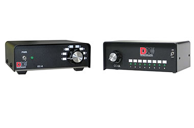
Using the DXE-EC-8 One of Eight Control Console, or DXE-CC-8A Antenna 8 Port Switch Console
Introduction
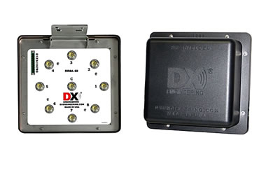
The DX Engineering RR8 series remote antenna switches (DXE-RR8 sereis -HP and -SD), when combined with the DXE-EC-8 One of Eight Control Console or DXE-CC-8A Antenna Switch 8 port Control Console, enables users to simultaneously select multiple antennas in stacked arrays of Yagi or broadside arrays. This brief guide provides instructions on how to properly connect and control stacked antennas and phasing lines to the RR8A series of switches.
Principles of Stacked Yagi Arrays
The DX Engineering RR8/EC-8 or CC-8A remote switching system, when combined with a simple diode matrix and 1/4 wavelength 75 ohm Q-sections, allows users to stack four antennas and obtain an SWR under 1.35:1 (when any combination up to three antennas is selected).
The eight ports on the RR8 remote antenna switch and the 8 positions on the EC-8 or CC-8A controller offer users flexibility in connecting many combinations of the four antennas. More information on stacking yagi antennas can be found in the ARRL Antenna Book.
Connecting Multiple Yagi Antennas
Since the eight ports on the RR8 enable so many combinations for stacked antennas, we have created an example to illustrate one possibility of this versatile antenna switch.
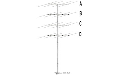
Example: An amateur radio operator has a tower with four stacked Yagi antennas as symbolized in Figure 1. After modeling the possible antenna combinations, the operator decides on the arrangement shown in Table 1. From that, he creates Table 2 as a matrix to track the association of ports on the RR8, switches on the CC-8A controller, and antennas on the stack. To make switching easier, he then creates a diode matrix as shown in Figure 2. Finally, he attaches the feedlines according to the Guidelines for Switching Stacked Yagi Antennas.
To connect the antennas in this example, refer to Tables 1 and 2 and Figures 2 and 3 and the Guidelines for Switching Stacked Yagi Antennas, and then do the following:
1. Determine how many antennas you want to stack.
Note: You can connect up to 4 antennas, but only 3 can be selected individually or simultaneously. In this example, Antenna B is selectable in a stack, but not independently.
2. Create a matrix like Table 2 to assign antennas to the proper ports and switches.
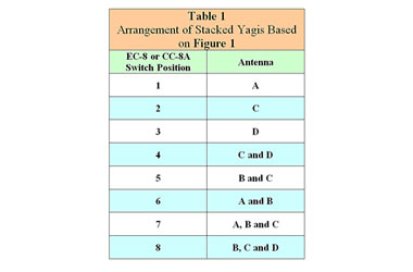
Table 1
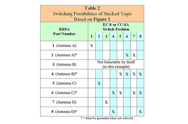
Table 2 - Control Matrix for the RR8A Ports
3. Create a diode matrix (see Figure 2) to configure the switching arrangement on the EC-8 or CC-8A. Use 1N4001 through 1N4007-type diodes. The diode matrix can be built around the control cable plug on the CC-8A or internally on the EC-8. Figure 2 depicts the diode logic determined in Table 2. Control position 1,2 &3 all pass through single diodes and select single antennas. Control position 4, 5 & 6 each connects to 2 diodes and select 2 antennas simultaneously. Control position 7 & 8 each connects to 3 diodes and select 3 antennas simultaneously.
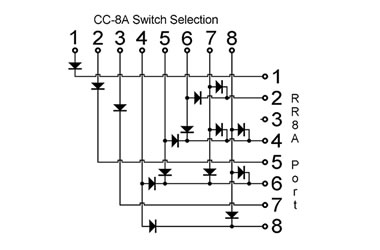
Figure 2 - CC-8A Diode Matrix shown
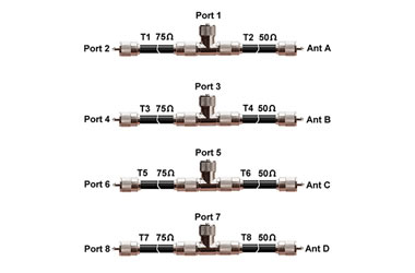
Figure 3 - Coaxial Cables & T's
4. Sketch a diagram of the coaxial feedline connections (refer to Figure 3).
5. Cut the feedlines to the proper length and attach them so that the connectors face downward (see the RR8 sereis user manual).
===================================
Guidelines for Switching Stacked Yagi Antennas
1. Stacked arrays must be identical antennas on the same band.
2. Feedlines connecting each antenna to the RR8 must be the same length. These 50 ohm transmission lines can be any length, but the length for each must be the same.
3. The 75 ohm transmission lines must be electrically 1/4-wavelength. RG-11 is acceptable even at high power. The end directly connected to the RR8 provides the connection for stacked configurations and must be grounded when not selected. This is accomplished by soldering in jumpers inside the RR8 unit, as described in the RR8 manual, on the even numbered ports as described in this example.
4. The junctions of the 75 ohm and 50 ohm cables must be made with T-connectors mounted directly to the RR8 connector.
5. Establish a numbering convention for RR8 ports; i.e., T-connectors go to odd-numbered ports and 75 ohm Q-sections connect to even-numbered ports.
6. T-connector ports cannot be grounded, they must “float” when not selected so they do not have jumpers. Ports connected by 75 ohm line must be grounded when not selected do have jumpers as mentioned above. This is accomplished by configuring the internal jumpers on the RR8 as described in the RR8 user manual.
===================================
Antennas that are not stacked can be used on separate bands, and every RR8 port can be used for any antenna. Each stacked antenna requires two ports on the RR8; antennas that are not stacked require only one port.