Back to Main Tech Support Page

Ask a Question
Technical Questions
Can't find an answer in our Help Center? Submit a question, and we'll get back to you soon.
Need Business/Order Related Support?
Search our Help Center
Get answers to business and order questions from our experienced Customer Service representatives.
Website Feedback
How are we doing? We really are interested in knowing how you feel about DX Engineering. Contact us with your comments - good, bad, great, so-so, or whatever. We want to hear from you!
Modifications to the M2 model 40M4LLDD
Modifications to the M2 model 40M4LLDD
Dual Driven Linear Loaded 40 Meter 4 Element Yagi Antenna
James Jones, AB4D
Front Royal, VA
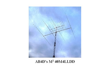
The advantage to the M2 dual driven linear loaded design is increased usable bandwidth, and near full size antenna performance in a smaller size footprint. Using the "Full Band" settings provided in the manual, the antenna covers the entire 40 meter band with an SWR below the advertised max SWR of 2:1. This has been confirmed on my installation. The measured SWR is 1.5 on the lower band edge at 7.000 MHz, 1.2 at the upper band edge of 7.300 MHz, and exhibits a nice smooth curve bottoming out around 1.1 on 7.180 MHz.
The antenna is currently fixed towards Europe, and I consistently receive “Big Signal” comments from stations on the other end when I am using just 200 watts. At legal limit, I've been told I am the loudest station heard!
I notice the bulk of U.S. stations are usually given 5/9 when running phone, while I receive 5-20+ over S-9 signal reports. I’m copying stations easily as well. As expected, the M2 40M4LLDD antenna works just as well on receive. In comparison to a ladder line fed 120 foot inverted V mounted at 70 feet, the M2 beam has significant better receive in the direction it is pointed. I've seen as much as 7 S-units in difference on receive when monitoring some European stations and switching between the two antennas.
In my opinion, the M2 40M4LLDD antenna as delivered from M2 has two major weaknesses that require entire part changes, and two of the supplied items that require modification or additions for the improvement of mechanical performance.
The modified antenna is working very well from both a performance and mechanical standpoint. Recently, my location experienced several periods of high winds in the 40+ mph range, and a freezing rain event that also coated the antenna with a 1/4 inch layer of ice, the antenna was totally unaffected. I believe the mechanical modifications will certainly increase the long term survivability of the antenna.
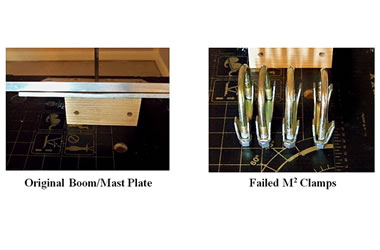
The first weakness is the boom to mast plate and associated clamps. The plate supplied by M2 for the antenna is an 8" x 8" x 1/4” thick aluminum plate. I believe the supplied plate is totally inadequate to support a 140 pound antenna that includes a 42 foot boom. The weight of the antenna alone, puts over 2 pounds per square inch of dead load on the factory supplied plate, before any wind/ice loading or twisting motion is factored into the equation. The factory supplied plate distorted during my initial installation of the antenna.
To replace the supplied plate, I opted for the DX Engineering DXE-BMP-3C Boom Mounting Plate. The DX Engineering 24" x 18" x 1/4” thick plate offers nearly seven times more surface area than the M2 factory 8" x 8" plate (432 inches of surface area versus a mere 64 inches), and results in just a little over 5 ounces per square inch of load on the new plate, effectively, reducing the dead load nearly 65%.
The four supplied clamps to secure the boom to mast plate to the mast are also subject to failure. The M2 supplied clamps are gold irradiated stamped steel clamps. Those clamps failed under the weight and pressure of the antenna, bending the stamped steel clamping surfaces outward, causing the clamps to slip. To replace the supplied clamps, I opted for the DXE-SDS-200P DX Engineering Super-Duty Saddle Clamps and the Super-Duty Saddle Clamp Armor Coated Bolts. That combination had both the strength and a much larger clamping surface to secure the antenna to the mast without slippage or failure.
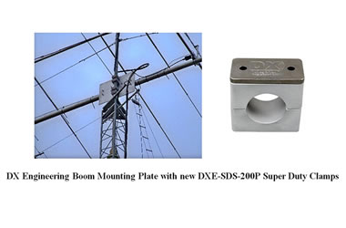
To complete the boom/mast assembly, I also upgraded from the two M2 supplied stainless steel boom to plate clamps to four DXE-SAD-300B DX Engineering Saddle Clamps. Although, I did not have any issues with the two clamps supplied by M2. Using four boom clamps rather than two, allowed me to spread the weight of the antenna more evenly along the new boom plate. The installation is now very solid.
The third improvement I made was to the boom support guy. The antenna is supplied with 5/16” Dacron rope to support the boom. The rope's safe working load varies, depending on the source. Reports vary from 281 pounds to 1700 pounds as a safe working load. Variables and unknowns are not good in relation to building reliable antenna support systems. On an antenna this large, it is critical to use something that has a known rating. Rather than using the supplied rope, I opted for 2100 pound rated Phillystran supplied by DX Engineering (PHI-HPTG-2100I), installed with three clamps per end, DXE-1037675 Rope Thimbles, and DXE-H165 DX Engineering Guy Caps to prevent contamination.
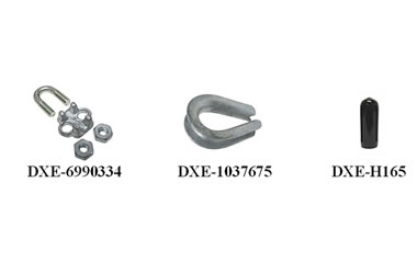
The final parts I improved were the M2 supplied Phillystran support guys for the elements/linear loading lines and the turnbuckles. The instructions call for the Phillystran lines to be secured with only two rope clamps. Past experience shows that others have seen similar lines slip when using only two clamps. I added a third clamp, like the DXE-6990334 DX Engineering Guy Lines Clamps, to each support end to alleviate any possible slippage.
The turnbuckles were the final parts that required improvement. The turnbuckles supplied by M2, have a hook on one end (left hand thread) and an eye on the other (right hand thread). They install with the hook on the center support post and the Phillystran support line for the elements through the eye. The manual for the antenna shows a jam nut on the hook end, which would be appropriate to prevent a turnbuckle from losing its tension. However, the turnbuckles are supplied with the jam nut on the eye end. This arrangement can allow the turnbuckle to loosen because the Phillystran is not stiff enough to prevent rotation. The same situation exists on the boom support turnbuckle as well. To resolve the turnbuckle issue, I added a jam nut to the hook end as well, so both ends could be secured to prevent a loss of tension.
I found that all of the parts I procured from by DX Engineering have fully exceeded my expectations. The availability of these parts made for a very secure and much improved installation of this large antenna.
---------------------------------------------------------------------------------------------
AB4D: My interest in radio began in the fall of 1972 with a gift from my parents, a Lafayette Radio 10 channel VHF/UHF scanner purchased from the long defunct Lafayette Radio. I was intrigued by the "magic" of radio and radio scanning. I was into scanning and listening to AM Broadcast DX.
In December 1993 I was granted the call sign of KE4IAQ. Subsequently, I upgraded to Tech Plus, then passed the General Class and Advanced Class tests and was granted the new call KU4BV. Soon thereafter, I upgraded to Amateur Extra, obtaining the call of AF4BL. In April 1997, I obtained the call of AB4D.
The current station consists of an Icom IC-7700, Kenwood TS-830S, Yaesu 1000-D and Yaesu 1000-Mark V for HF, Yaesu FT-847 for VHF/UHF, Yaesu Quadra Amplifier and an Alpha 9500 amplifier. Antennas: Hy-Gain TH-11DX at 83 Feet, M2 5 element Yagi for Six Meters at 79 Feet, M2 Dual Driven Linear Loaded 4 element Yagi for 40 meters at 74 Feet.
---------------------------------------------------------------------------------------------
Opinions expressed are those of the author and not necessarily those of DX Engineering.
Please direct any questions about specific clamp conversion details to the author:
James Jones, AB4D
Front Royal, VA
AB4D@aol.com